Transformer Sizing: Matching kVA Rating to Actual Load
News Details
A transformer that is too small runs hot, ages quickly and trips on overload. One that is too large costs more than the project needs and often runs at low load, where efficiency and power factor are poor. Transformer sizing is the step that prevents both problems.
This guide explains how to move from a list of connected equipment to a defensible kVA rating, and which site conditions should change that figure before you place an order.
Why capacity is rated in kVA
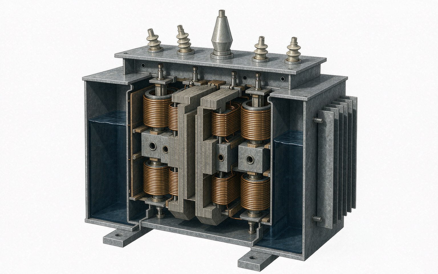
Transformer capacity is expressed in kVA rather than kW because the winding must carry both active and reactive power. The copper heats up either way, so the sizing result is always an apparent power figure, and the power factor of your load decides how much kVA a given number of kilowatts will demand.
Transformer load calculation: start from demand, not nameplates
The connected load is the sum of every rating on every nameplate. The load a transformer actually carries is lower, because equipment does not all run at full output at the same time. Therefore, the first task is a realistic transformer load calculation: list each load, record whether it is continuous, intermittent or a peak-impact load, and estimate how much of it runs at the same time.
Getting this estimate right matters more than any other input. A generous assumption oversizes the unit; an optimistic one leaves the transformer overloaded from day one.
How to run a transformer kVA calculation
Once the design demand is clear, express it in kVA. For a balanced three-phase system:
kVA = (√3 × line voltage × line current) ÷ 1,000
For a single-phase load, drop the √3 factor. Where the load is given in kW, divide by the power factor instead.
Converting kW to kVA with power factor
A load of 800 kW at a power factor of 0.80 requires 800 ÷ 0.80 = 1,000 kVA before any allowance is added. At 0.95, the same 800 kW needs only about 842 kVA. This is why power factor correction often shrinks the transformer a project needs, and why kW alone is never enough to size one.
Applying demand factor and diversity factor
Demand factor accounts for equipment that does not operate at full rating. Diversity factor accounts for loads that peak at different times of day. Both reduce the figure you calculated from nameplates, and both depend on how the facility actually operates rather than on a universal constant.
Use the real operating profile of the plant or building, and keep the reasoning documented. When two people size the same project and reach different ratings, the difference is almost always in these two factors.
Sizing for motor starting current
Large motors draw several times their running current during starting. This surge causes voltage dips and thermal stress, so the transformer must tolerate the starting duty, not just the running load. Check the largest motor, its starting method and whether several motors can start together. Soft starters and variable frequency drives reduce the impact, but the transformer impedance and the allowable voltage drop still decide whether starting is acceptable.
Setting transformer spare capacity
Some headroom is normal because loads grow and starting currents are higher than running currents. Common practice allows roughly 20 to 30 percent above the calculated maximum demand. Beyond that, extra capacity mostly costs money and pushes the transformer into low-load operation, where efficiency is worse.
If expansion is planned, size for the final stage or specify a unit that can be upgraded later, instead of adding a large margin now. Also avoid double counting: do not add a generic safety margin to the connected load and then apply a growth allowance on top without checking how the demand figure was built.
Derating for high ambient temperature and altitude
Ratings assume a reference ambient temperature and altitude. In a hot climate the unit must be derated; at high altitude, thinner air cools the windings less effectively and the rating drops again. Indoor dry-type units also depend on room ventilation, and enclosures restrict airflow.
These adjustments are not optional. A 1,000 kVA unit applied at 45 °C ambient will not deliver 1,000 kVA continuously, so confirm the derating basis with the manufacturer in writing.
Matching the result to standard transformer kVA ratings
Transformers are built in standard ratings. After the calculation, select the nearest standard rating above the final figure. Common distribution ratings run through values such as 100, 250, 400, 630, 800, 1,000, 1,250, 1,600 and 2,000 kVA, with the exact range depending on the standard and the manufacturer. Avoid choosing a rating far above the calculated value just because it is available; long-term light-load operation wastes both energy and capital.
Harmonic loads and the K-factor
Variable frequency drives, UPS systems, LED lighting and data-centre equipment inject harmonic currents that increase losses and heating. Where non-linear loads are significant, the transformer may need a K-factor rating or an additional derating. Tell the manufacturer about these loads early; harmonic heating is invisible at commissioning and shows up later as shortened insulation life.
Transformer sizing for solar PV projects
In a solar PV plant, the transformer usually steps the inverter output up to the grid or collection voltage. Sizing follows the same kVA logic, with two PV-specific points. First, output follows irradiance, so the transformer spends much of its life at partial load, which makes no-load loss relatively more important. Second, verify the voltage ratio against the grid connection point, because the step-up ratio and tap range must match the actual grid voltage, not a nominal value.
What to send the manufacturer
A short, complete input list gets an accurate proposal faster than a long conversation.
| Input data | Why it matters |
|---|---|
| Calculated demand (kW) and power factor | Sets the kVA requirement |
| Primary and secondary voltage, frequency, phase | Fixes the winding configuration |
| Load profile, including motor starting | Confirms thermal and voltage-drop duty |
| Ambient temperature and altitude | Determines derating |
| Harmonic or non-linear loads | Determines K-factor or derating |
| Planned expansion | Decides the spare-capacity strategy |
| Applicable standard | Aligns the design and test basis |
Send these figures and ask for the routine test report with the offer. The sizing decision then becomes a documented engineering choice rather than a guess.


